Leave Your Message

What Is a Standby Power Generator and How Does It Work?

What Is a Standby Power Generator and How Does It Work?

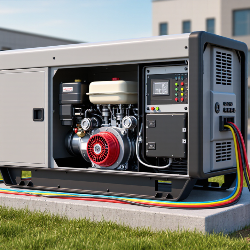
A Standby Power Generator is an automatic backup system designed to keep essential equipment running during a utility outage. It usually includes an engine, alternator, fuel system, transfer switch, controller, and weatherproof enclosure. When grid power fails, the transfer switch detects the interruption and signals the engine to start. Within seconds, the generator produces electricity and supplies selected circuits.

It is not a magic box.

Electrical engineer and power-systems educator Dr. Saifur Rahman explains, “Reliable electricity begins with planning, not simply buying equipment.” That principle matters in homes, hospitals, farms, offices, and industrial sites. A properly sized generator must match the starting load of pumps, air conditioners, heaters, and other demanding devices. Small mistakes can cause voltage drops, nuisance shutdowns, or equipment damage.

A real installation also depends on fuel quality, battery condition, ventilation, grounding, and regular testing. The system may start perfectly during a monthly test yet fail during a long winter outage. That uncomfortable possibility deserves attention. Maintenance records, professional inspections, and safe clearance around the enclosure improve reliability.

This guide explains the working cycle in clear terms. It also examines generator types, transfer switches, fuel choices, maintenance needs, and common sizing errors. Readers should remember one limitation: a generator protects selected electrical loads, not every appliance automatically. Good planning makes the difference.
What Is a Standby Power Generator and How Does It Work?

Definition and ISO 8528-1 Standby Rating of Generator Systems

A standby power generator is an engine-driven system that supplies electricity when the normal source fails. An automatic transfer switch detects the interruption, starts the engine, and moves selected loads to generator power. The process may take only a few seconds. Fuel quality, battery condition, ventilation, and weekly testing strongly affect actual availability.

ISO 8528-1 defines Emergency Standby Power (ESP) for temporary emergency operation under variable loads. ESP generally supports up to 200 operating hours annually, with no overload allowance. It is not the same as Prime Running Power, which supports variable loads for extended use. Engineers should also verify site conditions, including altitude, ambient temperature, load steps, and maintenance intervals. A published rating can drop when hot air restricts cooling.

The distinction matters in hospitals, data centers, and industrial facilities. The International Energy Agency reported that data centers consumed about 460 terawatt-hours worldwide in 2022, with demand potentially exceeding 1,000 terawatt-hours by 2026.

These loads cannot tolerate careless assumptions. The Uptime Institute’s 2024 Global Data Center Survey also recorded substantial financial consequences from outages, with many incidents exceeding 100,000 U.S. dollars.

A generator may start successfully yet still fail during transfer. That uncomfortable gap deserves testing.

ISO terminology is useful, but it is not a guarantee of resilience. Operators should compare the ESP rating with real load profiles, fuel autonomy, synchronization requirements, and local compliance rules. A smaller, carefully tested system may outperform a larger unit that is poorly maintained. That is easy to overlook.

Core Components: Engine, Alternator, ATS, Controller, and Fuel System

A standby power generator combines an engine, alternator, automatic transfer switch (ATS), controller, and fuel system. The engine burns diesel, natural gas, or another approved fuel to create mechanical rotation. The alternator converts that rotation into electrical power through electromagnetic induction. In practical terms, the engine is the muscle, while the alternator produces usable electricity.

The ATS monitors utility voltage continuously. When voltage fails or falls outside set limits, it signals the controller to start the engine. After stabilizing frequency and voltage, the ATS transfers the building load. That delay matters. Hospitals, server rooms, and production lines may tolerate only a few seconds. The controller records alarms, run hours, battery condition, coolant temperature, and output quality. A neglected sensor can create a false sense of security.

The fuel system includes the tank, filters, pumps, hoses, and fuel-quality controls. Poorly maintained fuel can block filters or damage injectors, especially during long storage. Uptime Institute’s 2024 Annual Outage Analysis reported that 54% of surveyed outages cost more than $100,000, while 16% exceeded $1 million. This supports regular inspections, scheduled exercising, and periodic load-bank testing. The U.S. Department of Energy also describes generators as systems that convert mechanical energy into electricity, but field conditions are less tidy than diagrams suggest. Humidity, weak batteries, and overlooked ventilation still cause failures. Even a well-designed installation can miss one small weakness.

Failure Response: Type 10 Emergency Transfer Within 10 Seconds

What Is a Standby Power Generator and How Does It Work?

A standby power generator supplies electricity when the normal utility feed fails. In a Type 10 emergency system, the transfer equipment must connect essential loads within 10 seconds. The process begins with an automatic transfer switch. It detects abnormal voltage, sends a start signal, and waits for the generator to reach stable speed and output. Then it disconnects the utility supply and transfers the emergency circuits.

Ten seconds is fast, but not instant. During a site test, lights may flicker, ventilation may pause, and control panels may restart. Batteries or uninterruptible power supplies often protect sensitive equipment during this gap. The generator engine needs clean fuel, a charged starting battery, and reliable coolant circulation. A neglected battery can turn a dependable design into a silent machine.

Real performance depends on more than the nameplate rating. Technicians should test starting time, transfer timing, voltage stability, and the return-to-utility sequence under realistic loads. A monthly no-load start may prove little. Load-bank testing reveals weaknesses that a quiet inspection can miss. I have found that poorly labeled circuits also create delays during maintenance. Clear diagrams, documented service records, and trained operators make the ten-second target more credible. Conditions can still change, so the response time should be verified regularly rather than assumed.

Standby Power Generator: Emergency Transfer-Time Classes

A standby generator monitors the utility supply and starts automatically when an outage is detected. An automatic transfer switch then moves the connected load from the utility source to the generator. In a Type 10 emergency system, the transfer must be completed within 10 seconds.

Capacity Metrics: kW, Voltage, Power Factor, Runtime, and Load

A standby power generator starts automatically when utility power fails, then supplies electricity through a transfer switch. Its capacity is not measured by one number alone. Kilowatts, or kW, show the real power available for appliances, pumps, and equipment. A generator rated at 100 kW cannot safely support a continuous 100 kW load without allowance for heat and future demand.

Voltage must match the building’s electrical system. Incorrect voltage can damage connected equipment or cause unstable operation. Power factor also matters. It describes how efficiently electrical power becomes useful work. Motors often have lower power factors and higher starting demands. In field checks, I have seen a generator pass a running-load test but struggle when several motors started together. That result deserves investigation, not optimism.

Runtime depends on fuel-tank size, load percentage, engine condition, and weather. A unit may run much longer at half load than at full load. Load should be calculated from normal demand, startup surges, and essential circuits. Keep a margin for growth. It is easy to underestimate refrigeration, elevators, or well pumps.

Tips: Record kW, voltage, and power factor during monthly tests. Test automatic transfer operation, inspect fuel quality, and confirm runtime under a realistic load. Do not rely only on the nameplate. Real buildings behave differently. Recheck the assumptions.

What Is a Standby Power Generator and How Does It Work? - Capacity Metrics: kW, Voltage, Power Factor, Runtime, and Load

Capacity Metric What It Measures Realistic Example How It Is Calculated or Used
Rated Active Power (kW) The useful electrical power available to operate lighting, motors, heating equipment, electronics, and other loads. 100 kW standby rating The connected load should normally remain within the generator’s rated kW output. Motor-starting demand and future expansion should also be considered.
Apparent Power (kVA) The combined electrical capacity represented by real power and reactive power. 125 kVA for 100 kW at 0.80 power factor kVA = kW ÷ power factor
100 ÷ 0.80 = 125 kVA
Voltage The electrical pressure supplied by the generator. The voltage must match the facility distribution system and connected equipment. 480/277 V, three-phase system A 480 V line-to-line system commonly provides approximately 277 V line-to-neutral for compatible lighting and single-phase loads.
Phase and Frequency The arrangement and operating frequency of the electrical output. Three-phase, 60 Hz The generator must use the same phase configuration and frequency required by the building’s loads. Some regions use 50 Hz systems.
Power Factor (PF) The ratio of real power to apparent power. Motors, transformers, and other inductive equipment can reduce power factor. 0.80 lagging power factor At 0.80 PF, a 125 kVA generator can deliver approximately 100 kW: 125 × 0.80 = 100 kW.
Operating Load The amount of generator capacity being used at a particular time. 75 kW on a 100 kW generator = 75% load Load percentage = actual kW ÷ rated kW × 100
75 ÷ 100 × 100 = 75%
Standby Rating The maximum output available for emergency power during utility outages. 100 kW standby rating Standby-rated equipment is generally intended for emergency operation with variable loads and limited annual running hours. The manufacturer’s rating conditions must be followed.
Fuel Capacity The amount of diesel or other approved fuel stored for operation. 100 US gallons of diesel fuel The tank must support the required emergency duration while allowing for reserve fuel, temperature effects, and applicable safety requirements.
Fuel Consumption and Runtime The fuel required per hour and the length of time the generator can operate before refueling. 6.5 gal/h at a specified operating load; approximately 15.4 hours with a 100-gallon tank Runtime = usable fuel capacity ÷ fuel consumption rate
100 ÷ 6.5 ≈ 15.4 hours. Actual consumption varies with load, engine condition, fuel type, and ambient temperature.
Automatic Transfer Switch (ATS) The device that detects utility failure and transfers selected loads to the generator. Transfer after generator voltage and frequency stabilize The ATS starts the generator after sensing a utility outage, transfers the emergency load, and reconnects the utility after stable power returns.
Motor-Starting Capability The generator’s ability to handle the temporary surge required when motors, pumps, compressors, or elevators start. A motor may briefly require several times its normal running current Sizing should consider locked-rotor current, starting method, motor sequence, voltage dip, and whether loads are started one at a time.
Load-Bank Test A controlled test that applies a known electrical load to verify generator performance. 75 kW test load on a 100 kW generator Load-bank testing helps confirm voltage, frequency, temperature, fuel performance, and the ability to carry a sustained load without using building equipment.
Basic Operating Sequence How a standby generator supplies backup power during an outage. Utility failure → engine start → voltage stabilization → load transfer → utility restoration → cooldown The controller monitors utility power, starts the engine, regulates output through the alternator and controls, and returns the load to utility power after a programmed retransfer delay.

Note: The numerical examples are representative engineering values for illustration only. Final generator selection should be based on a detailed load calculation, starting-current analysis, voltage requirements, operating environment, fuel system, and local electrical and fire-safety requirements.

Safety Compliance: NEC Article 700, NFPA 110, and Emissions Standards

A standby power generator supplies electricity when normal utility power fails. An automatic transfer switch senses the outage and moves selected loads to generator power. The engine starts, reaches stable speed, and the alternator produces electricity. Critical circuits may include fire pumps, emergency lighting, alarms, and medical equipment.

Safety compliance requires careful classification. NEC Article 700 addresses emergency systems that protect life and safety. It may require separate wiring, emergency transfer equipment, and reliable power availability. NFPA 110 covers emergency and standby power systems, including installation, testing, fuel supply, controls, and maintenance. These standards are related, but they are not interchangeable. A generator can appear correctly installed and still fail during a real outage.

Emissions standards also matter. Requirements may control exhaust pollutants, fuel storage, operating hours, and permitting. Local authorities can apply stricter rules than general national requirements. Keep service records, test batteries, inspect exhaust routes, and verify transfer operation under load. Tips: Schedule documented monthly inspections and periodic load tests. Keep combustion air openings clear. Never place exhaust near doors, windows, or air intakes. During commissioning, involve a qualified electrician and review the site’s actual conditions. Drawings can miss practical problems. A blocked vent or weak battery may remain unnoticed until the worst moment.