Leave Your Message

Why Do You Need a Transfer Switch?

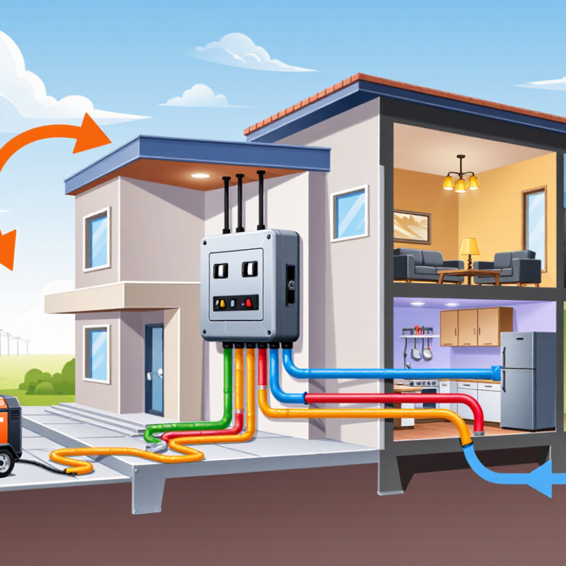
A Transfer Switch is a critical device that connects a building to an alternate power source. That source may be a portable generator, standby generator, or battery system. During an outage, it helps prevent electricity from flowing backward into utility lines. This protection supports utility workers and reduces dangerous electrical conflicts.

The device also makes power changes more controlled. Instead of moving cables beside a wet driveway, a user can switch between approved sources through a dedicated panel. A licensed electrician can inspect the wiring, confirm load capacity, and follow local electrical requirements. These details matter. A generator may run correctly but still overload a household circuit. That mistake can damage equipment, create heat, or cause a fire.

Small choices matter.

Transfer switches vary in design. Manual models require someone to operate the switch. Automatic models detect a power failure and transfer the load after a short delay. Neither option solves every problem. An automatic unit may need regular testing, while a manual unit depends on human attention during stressful conditions. The best choice depends on the building, generator, essential circuits, and installation environment.

This guide examines why a Transfer Switch is needed and how it supports safer backup power. It also considers practical limits, maintenance needs, and common installation concerns. However, no general article can replace an on-site electrical assessment. A qualified professional should verify compatibility before installation. That extra step may feel slow, but it can prevent expensive and dangerous mistakes later.
Why Do You Need a Transfer Switch?

What Is a Transfer Switch? Manual and Automatic Source Transfer Explained

Why Do You Need a Transfer Switch?

What Is a Transfer Switch? Manual and Automatic Source Transfer Explained

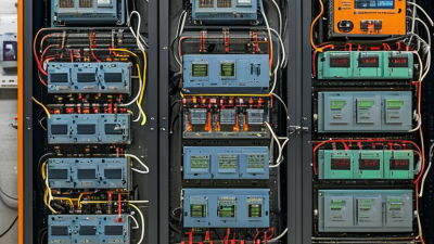
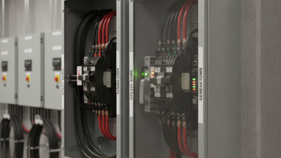
A transfer switch moves electrical loads between two power sources. Usually, one source is utility power, and the other is a generator. It is designed to prevent both sources from feeding the same circuit. That separation protects equipment and reduces dangerous backfeeding risks. Power fails. A manual transfer switch requires someone to turn a handle after checking the backup source. It is simple, visible, and often easy to inspect.

An automatic transfer switch detects a power failure and begins the changeover without constant attention. It can move selected circuits to a generator, then return them when utility power stabilizes. Timing matters. Sensitive systems may need a correctly sized switch, tested controls, and suitable generator capacity. During inspections, I check labels, enclosure condition, terminal tightness, and transfer sequence. A neat installation helps, but appearance proves little. The system must perform under a realistic load. My first inspection taught me that overlooked labels can slow safe operation.

Tips: Choose essential circuits, such as refrigeration, lighting, heating controls, or medical equipment. Ask a qualified electrician to verify ratings and wiring before energizing the system. Test a manual switch periodically, and record automatic test results. Keep operating instructions beside the enclosure.
How Transfer Switches Prevent Backfeed Under NEC 702.6 Safety Rules

Why Do You Need a Transfer Switch?

How Transfer Switches Prevent Backfeed Under NEC 702.6 Safety Rules

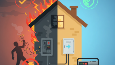
A transfer switch separates utility power from an alternate source, such as a generator. This separation prevents dangerous backfeed into energized utility lines. NEC 702.6 requires transfer equipment to prevent unintended interconnection between normal and alternate power sources. The rule is simple. The consequences are not.

During an outage, a generator can energize utility conductors if connected incorrectly. A lineworker may then face unexpected voltage while repairing a supposedly de-energized circuit. The U.S. Bureau of Labor Statistics recorded 145 fatal workplace injuries involving contact with electric current in 2022. That figure does not measure generator backfeed alone, but it shows why isolation cannot depend on memory or warning labels.

A properly installed switch uses mechanical or electrical interlocking. It allows only one source to feed the building at a time. Open-transition equipment briefly disconnects one source before connecting another. That small pause can protect workers and sensitive loads. Installation still requires correct sizing, grounding, inspection, and testing by a qualified professional. A clean panel is not proof of safe operation. In practice, overlooked neutral conductors or incorrect interlock settings can undermine an otherwise careful installation. Periodic testing matters because equipment can degrade, and assumptions can age badly.

Why Do You Need a Transfer Switch?

A transfer switch isolates the normal utility source from the alternate generator source before connecting the load. This prevents dangerous backfeed and supports the safety intent of NEC 702.6.

The chart uses nominal 120 V RMS source values for a simplified single-pole example. During normal operation, only the utility source is connected; during generator operation, only the generator source is connected. A properly installed transfer switch prevents both sources from being connected to the load at the same time.

Why NFPA 110 Type 10 Requires Emergency Power Within 10 Seconds

Why Do You Need a Transfer Switch?

NFPA 110 Type 10 requires emergency power to become available within 10 seconds after normal power fails. This requirement matters in hospitals, fire protection systems, communication centers, and other critical facilities. A transfer switch monitors the normal supply, signals the emergency generator, and moves selected loads to backup power.

The ten-second window sounds simple. It is not. The switch must detect voltage loss, send a start command, confirm acceptable generator output, and complete the transfer safely. Each step consumes time. A weak battery, delayed fuel delivery, poor wiring, or incorrect settings can push the system beyond the required limit.

Type 10 describes performance, not a particular transfer switch design. The complete emergency power supply system must work as a coordinated installation. During inspections, technicians should record start time, transfer time, load behavior, and return-to-normal operation. Testing under realistic conditions is valuable because a system may pass a brief demonstration but fail during a cold start or heavy load.

Small details matter. Loose control connections can create intermittent faults. An overloaded circuit can cause unexpected transfer behavior. Maintenance records also need honest comments, including delays and unresolved weaknesses. A clean report is useful, but an accurate report is safer. In practice, the ten-second requirement is not merely a number on a specification sheet. It is a response deadline that protects essential operations when ordinary power disappears.

How to Size a Transfer Switch by Amperage, Voltage, Poles, and SCCR

A transfer switch safely moves selected loads between utility power and a backup source. It prevents both sources from feeding the same circuit. Correct sizing begins with the load calculation, not the generator label. Add the running currents of connected equipment, then account for motors, heaters, and temporary starting surges. A 100-amp switch may be inadequate if a pump briefly demands much more current.

Voltage must match the system and the equipment. A 120/240-volt single-phase installation differs from a 208-volt three-phase system. Check the neutral arrangement carefully. Some systems require a switched neutral, while others do not. The number of poles follows this decision. A two-pole switch can transfer two energized conductors. A three-pole or four-pole design may be necessary for specific three-phase or separately derived systems.

Short-circuit current rating, or SCCR, is equally important. It indicates the fault current the switch assembly can withstand under defined conditions. Compare the switch SCCR with the available fault current at the installation point. An ampere rating alone cannot prove suitability. This detail is often underestimated. A quick estimate can mislead.

Before ordering, verify conductor size, overcurrent protection, grounding, enclosure conditions, and local electrical requirements. A qualified electrical professional should review the calculations and coordination. I would not rely on a catalog number alone. Field conditions, especially long feeder runs and large motor loads, can change the practical selection. Loose assumptions create expensive corrections later.

When to Choose Open, Closed, or Delayed-Transition Transfer Designs

Why Do You Need a Transfer Switch?

When to Choose Open, Closed, or Delayed-Transition Transfer Designs

A transfer switch moves electrical loads between normal and emergency sources. It also prevents unsafe source connections during the changeover. In hospitals, data rooms, and industrial facilities, timing matters as much as capacity. A poorly selected design can leave sensitive equipment exposed to voltage interruptions. During commissioning, technicians should verify source quality, interlocking, grounding, and actual load behavior. Nameplate data alone is not enough.

Open-transition transfer briefly disconnects the load before connecting the alternate source. It is simple, widely used, and often suitable for lighting, pumps, and general building loads.

Closed-transition transfer overlaps both sources for a controlled moment. This can reduce interruption, but it requires compatible sources, careful protection settings, and utility approval where applicable.

Delayed-transition transfer inserts a programmed pause between sources. That pause allows motors to stop and residual voltage to decay. It can prevent large inrush currents and unwanted mechanical stress.

The right choice depends on the load, not preference. I have seen teams select open transition because it costs less, then discover that control systems reset during testing. That assumption was too narrow. Closed transition may seem ideal, yet synchronization errors can create serious operational problems. Delayed transition also has limits; some processes cannot tolerate the waiting period. Review motor loads, ride-through requirements, source stability, and maintenance procedures with a qualified electrical professional. Test the complete sequence under realistic conditions, because real facilities rarely behave exactly like design drawings.